Another thing to check if you’ve got Hyper-V, Windows Hypervisor Platform, Virtual Machine Platform and Credential Guard and you’re still getting an error in VMware Workstation that “Virtualize Intel VT-X/RPT or AMD-V/RVI not supported on this platform” there is another place to check.
In Settings>Privacy & Security>Windows security>Device Security>Core Isolation
If this feature is enabled, it will enable a “hypervisor” and VMware Workstation/VirtualBox won’t have access to your CPU’s hardware virtualization features.
When Core Isolation is enabled, coreinfo.exe from SysInternals will show that a Hypervisor is present.
In my experience, Core Isolation can also cause a big performance hit on the host’s OS as well as games and apps.
It’s frustrating if you’re seeing the the message from VMware Workstation about Device Guard or Credential Guard or the similar one from VirtualBox.
But, there are a few thing to clarify before going off on a search for those devices. First, if you’ve got Hyper-V installed, that is the most likely culprit here and disabling or removing that feature should solve your issue.
This is great info, but what do you do about getting Workstation or VirtualBox to work?
Again, the most likely culprit is Hyper-V. Disabling or removing and a reboot should resolve this.
Disable or Remove Hyper-V
Disable Hyper-V
Open an elevated command prompt or PowerShell (right-click and select Run as Administrator)
Enter: bcdedit /set hypervisorlaunchtype off
Reboot. (To re-enable Hyper-V, open an elevated prompt and enter: bcdedit /set hypervisorlaunchtype auto and reboot.)
Remove Hyper-V
Go to Control Panel–>Programs and Features, select Turn Windows features on or off.
Expand Hyper-V, then expand Hyper-V Platform.
Uncheck Hyper-V Hypervisor.
Reboot. Please note that removing Hyper-V could affect the functionality of other features of Windows 10 such as Docker.
Windows Hypervisor Platform
While this is supposed to allow 3rd party virtualization to access the hardware virtualization on the host, it doesn’t seem to work for either Workstation or VirtualBox. Workstation gives the same standard Credential Guard message. VirtualBox is supposed to work per their changelog, but the communities have posts reporting failure and a bug report on it.
Disable Windows Hypervisor Platform
Go to Control Panel–>Programs and Features, select Turn Windows features on or off.
Uncheck WindowsHypervisor Platform
Reboot.
Disable Device Guard
Editing the Registry will disable this feature. Please make sure you have a backup of your system, as editing the Registry can result in an unusable or broken Windows.
Edit the following key: HKEY_LOCAL_MACHINE\SYSTEM\CurrentControlSet\Control\DeviceGuard\Scenarios\HypervisorEnforcedCodeIntegrity
Set: Name = “Enabled” Type =dword Data = 0
Reboot.
Alternately, you can use the Local Group Policy Editor to manage Device Guard.
Start gpedit.msc or find Local Security Policy from the start menu.
Expand Computer Configuration\Administrative Templates\System\Device Guard and change the state to disabled. If you see the same settings as below, you probably don’t have Device Guard enabled.
Credential Guard
Credential Guard is controlled via Group Policy, so it’s likely that if this is the issue, you’ll be unable to do anything about it yourself. You’ll need to contact your IT department to have this turned off. Again, Credential Guard is only available on Enterprise, Education, and IoT Enterprise. If you don’t have one of these versions, this isn’t the culprit.
Antivirus Utilities
There is one more culprit that could be causing the issue. Some antivirus software blocks hardware virtualization.
Check with your antivirus vendor to confirm this isn’t an issue and if there is a way to disable it on your AV software.
Due to the various builds of Windows 10, you might not find these settings in exactly the same place as described or shown.
Another culprit that uses a hypervisor is Core Isolation. Check the link above for more details, but if you’ve enabled Core Isolation, then you’ve got a hypervisor running.
To disable: Settings>Privacy & Security>Windows security>Device Security>Core Isolation
This one’s different. I’m taking a couple relatively modern workstations with 16GB or less RAM each and creating a Windows Active Directory domain environment. The cool thing here is with an extra switch we can add multiple physical systems into our virtual lab.
Keep in mind that you can still use a powerful workstation/server setup here and just skip setting up the second physical workstation and end up with the same setup as the VMware Workstation or VirtualBox tutorial.
Hardware used:
Workstation 1 (W1): Windows 10 Pro (1809) with Hyper-V, i5-4570, 16GB RAM, 500GB SSD, dual NICs (one onboard NIC, one SB3 1Gb NIC)
*workstation 1 requires 2 network cards.
Workstation 2 (W2): Windows 10 Pro (1809) with Hyper-V, i7-870, 12GB RAM, 256GB SSD, onboard NIC
optional: Ethernet switch (not used in your existing network environment), additional Windows 10 Pro, Windows Server, Hyper-V Server workstations
Download these ISOs and place then in an easily accessible location for later use.
Hardware Setup
Connect both NICs in W1.
NIC1 will be connected to your regular network environment
NIC2 will be connected to W2 directly, or to the optional switch
Assign a static IP to NIC2
IP Address: 172.16.1.100
Subnet mask: 255.255.255.0
Assign static DNS to NIC2
Primary: 172.16.1.201Hint: this will be the IP of our Windows domain controller
Connect NIC in W2 to switch**, if not directly connected to W1. **Most modern NICs no longer need a crossover cable to directly connect. If you’re having issues with a connection, a switch should resolve this, or a cross-over cable.
Virtual router Setup for Internal lab environment
Create virtual switches on W1
Start Hyper-V Manager
Click Virtual Switch Manager
Select External, and click Create Virtual Switch
Under Name, enter External Access, and assign the NIC connected in step 1 above to your regular network environment, and click OK.
Click select External,Create Virtual Switch again. Under Name, enter Internal Lab, select the second NIC and click OK.
Click OK to exit the Virtual Switch Manager.
Set IP Address for second NIC.
Go to Control Panel, Network and Sharing Center and click Change Adapter Settings
Right-click on vEthernet (Internal Lab) and select Properties.
Select Internet Protocol Version 4 (TCP/IPv4), then click Properties.
Enter the following IP information:
IP Address: 172.16.1.100 <– this is the address of W1 in the internal lab network
Subnnet mask: 255.255.255.0
Default gateway: 172.16.1.1 <– this is the address of the virtual router we will set up next
Click Ok. Click Close.
Create the virtual router VM
Return to the Hyper-V Manager and click New –> Virtual Machine.
Click Next to begin the wizard, enter the info in the fields and click Next when finished.
Name: Lab Router
Generation: Generation 1
Startup memory: 512MB, uncheck Use Dynamic Memory
Connection: Select External Access
Virtual Hard Disk: accept defaults and click Finish
Select Lab Router from Virtual Machines and click Settings.
Select Network Adapter and click Add
Select Internal Lab from Virtual Switch and click Apply
Select DVD Drive, then select Image file.
Click Browse and go to the location where the IPFire ISO is stored. Double-click the ISO. Click OK.
Start the Lab Router VM.
Click Start, then Connect.
Install IPFire.
Press Enter to begin the installation. Note: Window title will appear before instructions for this section.
Language selection: Press Enter to accept English
IPFire: Press Enter to Start installation
License Agreement: Press tab to move to license acceptance box, then press the spacebar to accept. Press tab and Enter to complete.
Disk Setup: Press Enter to accept and Delete all data
Filesystem Selection: Press tab and Enter to accept the default.
Congratulations: Press Enter to reboot
Configure IPFire Pre-config info.
While IPFire is rebooting, we need to determine which NIC’s MAC address is the External Lab’s.
In the Hyper-V Manager with Lab Router selected, click Settings.
Click on plus (+) next to Network Adapter External Access, then click Advanced Features to view the adapters MAC.
Leave this window open, or make note of the MAC as we will need it soon.
Configure IPFire
Keyboard Mapping: Press Enter to select the default mapping.
Timezone: Choose the correct timezone and press enter. Hint: pressing a letter will jump to that section. US Pacific (press P and arrow to PST8PDT) can be found this way quickly.
Hostname: Press Enter twice to accept the default, ipfire.
Domain name: Press Enter twice to accept the default.
Root password: Enter a memorable password, tab to the verification field, and tab again to OK. Press Enter. Hint: no characters will appear when entering the password.
Admin password: Enter a memorable password, tab to the verification field, and tab again to OK. Press Enter. Hint: no characters will appear when entering the password. Extra hint: for our lab, this can be the same password as the root account for simplicity.
Network configuration: network configuration type: GREEN + RED should already be selected.
Arrow key down to select Drivers and card assignments, press Enter
Assigned cards: GREEN: Press Enter to select. Hint: the GREEN network is our Internal Lab network.
Choose the card that does NOT have the MAC from step 6.3. Use the arrow key to highlight and press Enter
Assigned cards: use the arrow keys to highlight RED, and press Enter
Press Enter to select the remaining card.
Assigned cards: press tab to move and highlight Done. Press Enter
Arrow key down to select Address settings and press Enter
Address settings: GREEN. Press Enter to reconfigure
Warning: press Enter. Hint: we are not connected remotely, so this does not apply
Interface GREEN: IP Address: 172.16.1.1 Network mask: 255.255.255.0 Press tab to move between fields, press Enter when complete
Address settings: RED: Press Enter to reconfigure.
Down arrow key to select DHCP, press spacebar to select. Tab to OK and press Enter. Hint: our external network will use the existing network DHCP server
Address settings: Press tab to move to Done, press Enter.
Arrow key down to Done and press Enter. Hint: we do not need to set the DNS and Gateway settings, the DHCP option selected above in 9-2 will autopopulate this for the RED network.
DHCP server configuration: We will use the DHCP and DNS services on our Windows Server VM that we will set up later.
Tab to OK and press Enter to leave the IPFire DHCP server unconfigured.
Setup is complete: Press Enter. IPFire will reboot.
IPFire/Lab Router VM should remain running.
Close the Lab Router settings window, if needed.
Windows Server (Domain Controller) for Internal Lab environment
Create Windows Server VM
Return to the Hyper-V Manager and click New –> Virtual Machine.
Click Next to begin the wizard, enter the info in the fields and click Next when finished.
Name: Windows Server 1
Generation: Generation 1
Startup memory: 4096MB, uncheck Use Dynamic Memory
Connection: Select Internal Lab
Virtual Hard Disk: accept defaults and click Finish
Select Windows Server 1 from Virtual Machines and click Settings.
Select DVD Drive, then select Image file.
Click Browse and go to the location where the IPFire ISO is stored. Double-click the ISO. Click OK.
Install Windows Server 2016
Start Windows Server 1
Click Start, and then Connect.
Install Windows Server 2016
Click Next to begin the installation
Click Install now
Select Windows Server 2016 Datacenter Evaluation (Desktop Experience) and click Next.
Click I accept the license terms, then click Next
Click Custom: Install Windows only
Click Next, to accept the default installation location
Customize settings: enter a memorable Administrator password, reenter, and click Finish
Configure Windows Server 1 (WS1)
Press control+alt+end to log into WS1, or use the menu options: Action–>Control+Alt+Del
Go to the Control Panel, change Viewby to Small Icons
Click Network and Sharing Center
Click Change Adapter Settings
Right-click Ethernet and click Properties
Select Internet Protocol Version 4 and click Properties
Click Use the following IP address:
IP Address: 172.16.1.201
Subnet mask: 255.255.255.0
Default gateway: 172.16.1.1
Click Use the following DNS server addresses
Preferred DNS server: 172.16.1.201 Hint: We will setup AD, DNS, and DHCP on this server
Click OK, then click Close
Networks: when prompted, click Yes to allow your PC to be discoverable.
In Control Panel, go to System. Under Computer name, click Change Settings.
Click Change, enter WS1, as the computer name. Click OK. Click OK at the prompt
Click Close
Click Restart Now
Setup WS1 as a domain controller with DHCP
Start the Add Roles and Feature Wizard
Add the following roles:
Active Directory Domain Services
DHCP Services
DNS Services
Follow the wizard’s steps. All the defaults can be used for our lab purposes.
Promote: Add a new forest.
Enter the domain name, Hyper-LAB.net, and follow the wizard. Hint: you will get a warning about DNS, this will be resolved later.
DNS. We need to add a forwarder for our DNS settings.
From Administrative Tools (or Server Manager–>Tools), open DNS
Right-click on your server and click Properties.
Click the Forwarders tab
Click Edit, and add your external DNS servers like 4.2.2.1, 4.2.2.2, 8.8.8.8, and 8.8.4.4.
Click OK, when completed. Click OK, to close Properties.
Close the DNS Manager
DHCP
Double-click DHCP from Administrative Tools or Server Manager–>Tools
Expand IPv4 and right-click, click New Scope from the menu.
Enter a Name: Hyper-Lab client scope, click Next
Start IP address: 172.16.1.50
End IP address: 172.16.1.99
Length: 24 or Subnet mask: 255.255.255.0
Click Next
The remaining settings can be default for now.
When asked to configure scope options, select “Yes” and click Next.
Router/Default gateway will be the IP we used to configure the GREEN NIC, enter: 172.16.1.1. Click Add. Click Next.
Domain name and DNS should be pre-configured. You should see the server’s IP in IP address box, 172.16.1.201. Click Next.
WINS does not need to be configured at this time. Click Next.
When prompted to activate scope, select “Yes” and click Next.
Click Finish to complete the wizard.
Right-click on the server’s name under DHCP, and click Authorize from the menu. Right-click the server name and click Refresh and IPv4 should have a green circle with a white check mark
WS1 configuration is complete. You should be able to ping an IP address, ex: 4.2.2.2 as well as a DNS name: ex: http://www.google.com
Workstation 2 setup and configuration
After the successful configuration of WS1, a network prompt on W2 should appear
Verify DHCP is configured for W1, if no prompt
Networks: when prompted, click Yes to allow your PC to be discoverable
Ping will not work until we disable the firewall, or turn on file and print sharing for the Private network.
Set a static IP for W2:
IP Address: 172.16.1.101
Subnet mask: 172.16.1.1
DNS: 172.16.1.201
Configure an External Virtual Switch
Create virtual switches on W1
Start Hyper-V Manager
Click Virtual Switch Manager
Select External, and click Create Virtual Switch
Under Name, enter Internal Lab, and assign the NIC and click OK.
If the network is set to public, we need to change it to private
Open an elevated Powershell
Set Internal Lab to private: Set-NetConnectionProfile -InterfaceAlias “vEthernet (Internal Lab)” -NetworkCategory Private Hint: If the Default Switch is set to Public, we need to change that one also
Set Default Switch to private: Set-NetConnectionProfile -InterfaceAlias “vEthernet (Default Switch)” -NetworkCategory Private
Enable firewall rules and delegation: Enable-WSManCredSSP -Role server
Set up Remote Desktop for W2
Go to Control Panel, click Category, then Small icons
Click System
Click Remote Settings, select Allow remote connections to this computer, uncheck Allow connections only from computers running with NLA
Click OK
Configure W1 to access W2’s Hyper-V Manager (optional, we can manage W2 via RDP or directly from W2)
When you try to connect with Hyper-V Manager you’ll receive an error from Hyper-V Manager that it’s either not running or you are not authorized.
Start an elevated PowerShell prompt on W1
You may need to set the Internal Lab network to private, then we need to add W2 to the hosts file and run winrm quickconfig:
Set Internal Lab to private: Set-NetConnectionProfile -InterfaceAlias “vEthernet (Internal Lab)” -NetworkCategory Private
Add W2 to the hosts file: Add-Content -Path C:\Windows\System32\drivers\etc\hosts -Value “`n172.16.1.101`tW2” Hint: the ` is not a single quote, but a grave, the grave/tilde key is left of the 1 key
Run quickconfig: winrm quickconfig Enter “y” to make the changes.
Go to Computer Configuration–>Administrative Templates–>System–>Credentials Delegation->Allow delegating fresh credentials with NTLM-only server authentication
Select Enabled. Click Show, enter wsman/W2. Click OK twice.
Connect to W2
In Hyper-V Manager, click Connect to Server
Select Another Computer, enter W2.
Select Connect as another user, enter W2\hyperlab1 and the password you set for this account on W2
Copy the Windows 10 ISO to W2 for setting up a new VM
Your basic lab is now setup. You can manage both Hyper-V systems from W1
You can add more Hyper-V “servers” to your network with a switch for the Internal Lab network between W1, W2, and the other servers, follow the steps for W2 with each new Hyper-V server.
Keep in mind that you can just use low-end workstations for clients in this scenario also. They just need to be added to the Internal Lab network’s switch.
I have a Ryzen 5 system that I wanted to install Windows Server 2019 to start experimenting with. Unfortunately, Intel doesn’t offer Windows Server 2019 drivers for their I211 NIC. There’s quite a bit of info regarding it, but no easy solutions.
Note: I’m no AD expert, there are better, worse, and different ways to do this and you’re not required to use VMware Workstation.
Requirements: 16GB RAM minimum SSD or multiple HDDs Quad-core or better CPU with hardware virtualization enabled
Download the necessary software. Download the ISO for the OSes you’ll be installing. For this example, I’ll be using IPFire and the MSDN versions of Windows Server 2016 and Windows 10 Pro.
In Workstation, right-click My Computer and click New Folder. Enter a name like “Allin1 AD” and press Enter. Click your new folder to select it.
Create an internal network.
Click Edit–>Virtual Network Editor.
Click Change Settings, click Yes at the UAC prompt.
Click Add Network, select a network. For this example, we’ll use VMnet15. Click OK.
Under VMnet Information, verify that Host-only is selected.
Uncheck Connect a host virtual adapter to this network. *This will prevent your physical host from accessing the test environment.
Uncheck Use local DHCP service to distribute IP address to VMs. *We will use the Windows server’s DHCP and DNS for this environment.
Change the subnet address to 192.168.15.0 **Any IP subnet can be used here. To prevent confusion, use a unique IP range. 10.0.15.0, 10.15.0.0, 172.16.0.0 and 172.16.15.0 are all alternative options. Choose an appropriate subnet. For the labs purposes, a 255.255.255.0 subnet is acceptable. Click Apply.
Verify your settings for VMnet15 and click OK.
Create your IPFire Router VM
Click File–>New Virtual Machine or CTRL+N.
Select Custom and click Nextto begin the New Virtual Machine Wizard.
Click Next, the default hardware compatibility is fine.
Select Installer disc image file (iso) and click Browse. Go to the location from step 1.3 where the IPFire ISO is located.
Select the ISO and click Open.
Click Next.
Select Linux as the guest OS and click Next. *IPFire is built from scratch and not based on any Linux distro.
Enter IPFire for the VM’s name. Select the appropriate location for your VM. For this document, the name is ipfire-wpdoc and the location is C:\VMs\ipfire-wpdoc
Click Next.
One processor is enough for our IPFire router, click Next.
Network type. Select host-only networking and click Next.
Click Next to select the default I/O controller type.
Click Next to select the default disk type.
Click Next to create a new virtual disk.
Change the disk size to 4GB and click Next. *2GB is the minimum, 4GB is recommended for logs and add-ons. See 4.9 above.
Click Next to accept the default disk file name and location.
Click Customize Hardware.
Click Add…,
Click Network Adapter.
Click Finish.
The new network adapter, network adapter 2, will be selected. Select NAT or Bridged for the network connection. **NAT will provide a more isolated environment, where bridged will allow the IPFire VM an IP address on your host’s network. NAT will be used for this document.
Click Advanced. Click Generate under MAC Address. Make note of this address. We will need the address when assigning network types in the IPFire installation. Click OK.
Click Close.
Click Finish.
Click Edit Virtual Machine Settings
Click Network Adapter
Click Custom, select VMnet15, click OK.
Drag the IPFire VM into the folder created in 2.1 above.
Install IPFire
Click Power on this virtual machine.
Click the IPFire splash screen and press Enter.
Press Enter to accept the default language selection.
Press Enter to Start Installation.
Press Tab, press the spacebar to select I accept this license. Press Tab again and press Enter.
Press Enter to Delete all data.
Press Enter to accept the default file system.
Press Enter to reboot.
Configure IPFIre
Press Enter to select the default keyboard layout.
Change the timezone. For this document PST8PDT will be used. Press Enter.
Press Enter twice to accept the default hostname
Press Enter twice to accept the default domain
Root password. Enter a password and press Enter twice. Press Enter to continue.
Enter a password and press Enter twice. *this is for the admin password, it can be the same for simplicity.
Press Enter to continue.
Use the arrow key to move down to Drivers and card assignments, press Enter.
Green — This is our internal test environment network. It will have no direct access to the Internet or the host’s network.
Press Enter to select
Compare the MAC addresses and use the one that was notgenerated in step 4.16.3.2.
Use the arrow keys to select the correct interface and press Enter. To move between fields, use the Tab key.
Red — this will allow the test environment external access via the NAT network.
Use the arrow key to select Red and press Enter.
There should only be one interface left to select. Press Enter.
Both network cards should now be assigned. Use Tab to move to Doneand press Enter.
Tab to Address Settingsand press Enter.
Press Enter to reconfigure the Green interface.
Press Enter to acknowledge the warning. We are not connected remotely, so this does not apply.
Since we are using the 192.168.15.0 subnet, we will assign a 192.168.15.1 IP address to the Green interface as it will be our gateway IP address. The default subnet mask does not need to be changed. Press Enter three times to accept the IP, subnet, and return to Address Settings.
Use the arrow key to select Red. Press Enter.
The Red interface will get an IP address from Workstation’s NAT. Using the arrow keys and spacebar, select DHCP. Use Tab to move to OK and press Enter.
Use Tab to move to Done and press Enter.
DNS and Gateway settings are only needed if using a static IP. Since we are using DHCP, there is nothing to change here. Tab to Done and press Enter.
We will be using Windows DHCP so we do not need to enable IPFire’s DHCP server. Tab to OK and press Enter.
Setup is complete. Press Enter.
Login with rootand verify that you can ping an external IP address like 4.2.2.2 or 8.8.8.8. Press CTRL+C to break the ping. If unable to ping, verify the network configuration is correct above.
Create a Windows Server 2016 VM.
Press CTRL+N, select Custom, click Next.
Click Next, the default hardware compatibility is fine.
Select Installer disc image file (iso) and click Browse. Go to the location from step 1.2 where the Windows Server ISO is located.
Select the ISO and click Open.
Click Next.
Click Next to skip the Easy Install Information. Click Yes to accept the product key prompt.
Enter a VM name and location. For this document, the name is W2016DC1 and D:\VMs\Virtual Machines\W2016DC1
Click Next to select the default BIOS.
Select One Processorand Two Cores. Click Next.
Set RAM to 4096MB. If you have more than 16GB of RAM, you can increase to 6 or 8GB, if needed. Click Next.
Select use host-only networking and click Next.
Click Next to select the default I/O controller type.
Click Next to select the default disk type.
Click Next to create a new virtual disk.
Change the Maximum disk size to 80.0 GB. Click Next
Click Next to accept the default disk file name and location.
Click Finish.
Click Exit virtual machine settings.
Click Network Adapter.
Select Custom, VMnet15, and click OK
Install Windows 2016
Install Windows as you normally would.
Configure Windows Server and Domain
Enter the IP information. The IP needs to be on the same subnet as configured for the GREEN network. EX: 192.168.15.200, GW: 192.168.15.1, DNS: 127.0.0.1 since we’ll be creating a domain controller with DNS and DHCP services. *Remember to use the IP address entered in step 6.11.3 for the gateway address.
You should be able to ping an IP address like 192.168.1.15 and 4.2.2.2, but not a DNS name.
Change the name of your server and reboot.
Start the Add Roles and Feature Wizard 1. Add the following roles: –Active Directory Domain Services –DHCP Services –DNS Services 2. Follow the wizard’s steps. 3. Promote: Add a new forest. 4. Enter your domain name and follow the wizard. –you will get a warning about DNS, this will be resolved later.
Configure DNS and DHCP
DNS. We need to add a forwarder for our DNS settings.
From Administrative Tools, open DNS
Right-click on your server and click Properties.
Click the Forwarders tab
Click Edit, and add your external DNS servers like 4.2.2.1, 4.2.2.2, 8.8.8.8, and 8.8.4.4.
DHCP
Double-click DHCP from Administrative Tools
Expand IPv4 and right-click, click New Scope from the menu.
Enter an IP range, ex: 192.168.211.50 to 192.168.211.100
The remaining settings can be default for now.
When asked to configure scop options, verify “Yes” and click Next.
Router/Default gateway will be the IP we used to configure the GREEN NIC, ex: 192.168.15.1
Domain name and DNS should be pre-configured. You should see the server’s IP in IP address box, ex: 192.168.15.200
WINS does not need to be configured at this time.
When prompted to activate scope, verify “Yes” and click Next.
Click Finish to complete the wizard.
Right-click on the server’s name under DHCP, and click Authorize from the menu. Refresh and IPv4 should have a green circle with a white check mark
Note: I’m no AD expert, there are better, worse, and different ways to do this and you’re not required to use VirtualBox.
Requirements:
16GB RAM minimum
SSD or multiple HDDs
Quad-core or better CPU with hardware virtualization enabled
Download the necessary software. Download the ISOs for the OSes you’ll be installing. For this example, I’ll be using IPFire and MSDN versions of Windows Server 2012R2 and Windows 10 Pro.
Click New, enter the name of your router, ie “IPFire”
Change the OS to Linux, Ubuntu 64bit is fine as the version. Click Next.
Enter 512MB for memory. Click Next.
Click Create for a new virtual HDD and select VDI. Click Next.
Select Dynamically allocated and click Next.
Change the location here if necessary. The 10GB default is large enough, click Create.
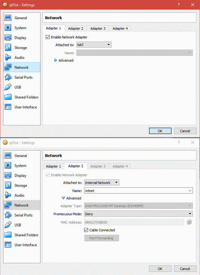
Once created, click Settings and then click Network. We need to modify the networking options.
Adapter 1 should be set to NAT or Bridged.
Adapter 2 needs to be enabled and set to Internal Network. **Make note of the MAC address for adapter 2. You can find it by expanding the Advanced tab.**
Click OK.
Mount the IPFire ISO and install
Click Settings on the IPFire VM. Click Storage.
Click “Empty” next to the CD icon. Click the CD icon next to the far right to mount the ISO.
Select “choose a virtual optical disk file” and browse to the ISO’s location.
Select to mount. Click Ok to close the window.
Power on the VM.
Follow the IPFire prompts. Press enter to select, tab to move between selections, and the space bar to select check boxes.
All defaults can be used.
Configure IPFire
Select the keyboard mapping. I’m using “us.” Press Enter to accept.
Set your timezone. By pressing the first letter of your timezone, you can jump to that section. Select the correct timezone via the arrow keys and press Enter to accept.
Enter a host name, the default is fine for our lab. Press Enter twice.
The default domain is fine for our lab, press Enter twice to continue.
Enter the root password and press Enter each time and once more to continue.
Do the same for the admin password. Password can be the same for both for our lab purposes.–Network Configuration–
Press Enter for “network configuration type”
Select “Green + Red” and press Enter
Arrow down to “drivers and card assignments.” and press Enter.
Green: This is our internal network. Press Enter to select. Compare the MAC and select the correct interface. Press Enter to select the Interface.
Red: This is our internet facing network, NAT or Bridged. Select RED, press Enter, and press Enter again to select the remaining interface.
Tab over to done and press Enter.–Address Settings–
Press Enter to select. GREEN:
1. Select GREEN and press Enter.
2. This is a new private, virtual network for our lab. Select a different IP subnet than your host network to avoid confusion.
3. The IP warning can be ignored as we are not logged in remotely. In this example, the subnet is 192.168.211.1/24. Since this will be the gateway, we can use 192.168.211.1. The subnet mask does not need to change.
4. Press Enter until you return to the GREEN/RED menu. RED:
1. Select RED and press Enter.
2. Select DHCP. This interface will get the IP from the VBox NAT or your physical network’s DHCP server. You can modify the hostname here if necessary.
3. Tab to Done and press Enter. –DNS and Gateway settings–
1. DNS and Gateway settings are only needed if using a static IP. Since we are using DHCP, there is nothing to change here. Tab to Done and press Enter.–DHCP Configuration–
We will be using Windows DHCP instead of IPFire’s. Tab to OK and press enter without enabling DHCP. Press Enter to close setup.
Create Windows Server 2012 R2 VM
From the VBox main men, click New.
Enter a name, ex: “WS2012R2”, select the appropriate type (Windows 2012) and version (64-bit). Click Next.
Set RAM to 4096MB. If you have more than 16GB of RAM, you can increase to 6 or 8GB, if needed. Click Next.
Create a new virtual hard disk, click Create.
Select VDI and click Next.
Select Dynamically allocated, and click Next.
Enter 80GB and click Create.
Click Settings, then click Network.
Select Internal Network.
Select Storage. Click the CD under storage devices, then click the CD icon to the left of Optical Drive.
Select Choose virtual optical disk file. Browse and select your Windows Server ISO.
Click OK.
Install Windows Server 2012
Install Windows as you normally would.
Configure Windows Server and Domain
Enter the IP information. The IP needs to be on the same subnet as configured for the GREEN network. EX: 192.168.211.200, GW: 192.168.211.1, DNS: 127.0.0.1 since we’ll be creating a domain controller with DNS and DHCP services.
You should be able to ping an IP address, but not a DNS name.
Change the name of your server and reboot.Start the Add Roles and Feature Wizard
1. Add the following roles:
–Active Directory Domain Services
–DHCP Services
–DNS Services
2. Follow the wizard’s steps.
3. Promote: Add a new forest.
4. Enter your domain name and follow the wizard. –you will get a warning about DNS, this will be resolved later.
Configure DNS and DHCP
DNS. We need to add a forwarder for our DNS settings.
1. From Administrative Tools, open DNS
2. Right-click on your server and click Properties.
3. Click the Forwarders tab
4. Click Edit, and add your external DNS servers like 4.2.2.1, 4.2.2.2, 8.8.8.8, and 8.8.4.4.
DHCP
1. Double-click DHCP from Administrative Tools
2. Expand IPv4 and right-click, click New Scope from the menu.
3. Enter an IP range, ex: 192.168.211.50 to 192.168.211.100
4. The remaining settings can be default for now.
5. When asked to configure scop options, verify “Yes” and click Next.
6. Router/Default gateway will be the IP we used to configure the GREEN NIC, ex: 192.168.211.1
7. Domain name and DNS should be pre-configured. You should see the server’s IP in IP address box, ex: 192.168.211.200
8. WINS does not need to be configured at this time.
9.When prompted to activate scope, verify “Yes” and click Next.
10. Click Finish to complete the wizard.
Right-click on the server’s name under DHCP, and click Authorize from the menu. Refresh and IPv4 should have a green circle with a white check mark.
Note: You will get a certificate error when accessing the IPFire management page.
9. Adding Client VMs.
Nothing special here. Install Windows/Linux as usual. Make sure to select Internal Network for the VM’s network
10. Completion!
Here’s the money shot:
-VirtualBox
-IPFire VM
-WS2012R2 VM – domain controller for sw.net, DHCP and DNS roles
-Win10 VM – joined to sw.net, displaying IPFire’s web management page and network settings.